Johnson-controls TCGF24 User Manual

Browse online or download User Manual for Conditioners Johnson-controls TCGF24. Johnson Controls TCGF24 User Manual

  • Download
  • Add to my manuals
  • Print
  • Page
    / 4
  • Table of contents
  • BOOKMARKS
  • Rated. / 5. Based on customer reviews
Page view 0
Johnson Controls Unitary Products 362564-UTD-B-0708
TABULAR DATA SHEET
Outdoor Split System Air Conditioner 2 Thru 5 Tons
MODELS: TCGF24* THRU 60
14.5 SEER – R-410A, 1 PHASE
All dimensions are in inches. They are subject to change
without notice. Certified dimensions will be provided upon
request.
Physical and Electrical Data
MODEL TCGF24S41S1 TCGF30S41S1 TCGF36S41S1 TCGF42S41S1 TCGF48S41S1 TCGF60S41S1
Unit Supply Voltage 208-230V, 1φ, 60Hz
Normal Voltage Range
1
1. Rated in accordance with ARI Standard 110, utilization range “A”.
187 to 252
Minimum Circuit Ampacity 16.8 18.4 19.1 23.9 27.9 35.9
Max. Overcurrent Device Amps
2
2. Dual element fuses or HACR circuit breaker. Maximum allowable overcurrent protection.
25 30 30 40 45 60
Min. Overcurrent Device Amps
3
3. Dual element fuses or HACR circuit breaker. Minimum recommended overcurrent protection.
20 20 20 25 30 40
Compressor Type Scroll Scroll Scroll Scroll Scroll Scroll
Compressor
Amps
Rated Load 12.8 14.1 14.1 17.9 21.1 27.5
Locked Rotor 58 73 77 112 115 135
Crankcase Heater No No No No No No
Fan Motor Amps Rated Load .8 .8 1.5 1.5 1.5 1.5
Fan Diameter Inches 22 22 22 24 24 24
Fan Motor
Rated HP 1/8 1/8 1/4 1/4 1/4 1/4
Nominal RPM 1075 1075 850 850 850 850
Nominal CFM 2750 2800 3200 3600 3600 3700
Coil
Face Area Sq. Ft. 13.1 17.4 17.4 20.0 21.4 24.0
Rows Deep 1 1 1 1 1 1
Fin / Inches 23 23 23 23 23 23
Liquid Line Set OD (Field Installed) 3/8 3/8 3/8 3/8 3/8 3/8
Vapor Line Set OD (Field Installed) 3/4 3/4 3/4 7/8 7/8 1 1/8
Unit Charge (Lbs. - Oz.)
4
4. The Unit Charge is correct for the outdoor unit, matched indoor coil and 15 feet of refrigerant tubing. For tubing lengths other than
15 feet, add or subtract the amount of refrigerant, using the difference in length multiplied by the per foot value.
3 - 2 3 - 7 3 - 10 4 - 4 4 - 9 5 - 9
Charge Per Foot, Oz. 0.62 0.62 0.62 0.67 0.67 0.75
Operating Weight Lbs. 128 130 145 172 180 199
B
C
A
Unit
Model
Dimensions
(Inches)
Refrigerant Connection
Service Valve Size
A
1
1. Including Fan Guard.
B C Liquid Vapor
24 28 29 29
3/8”
3/4”30 36 29 29
36 36 29 29
42 34 33.6 33.6
7/8”
48 36 33.6 33.6
60 40 33.6 33.6
7/8”
2
2. Adapter fitting required for 1-1/8” line set.
Page view 0
1 2 3 4

Summary of Contents

Page 1 - TABULAR DATA SHEET

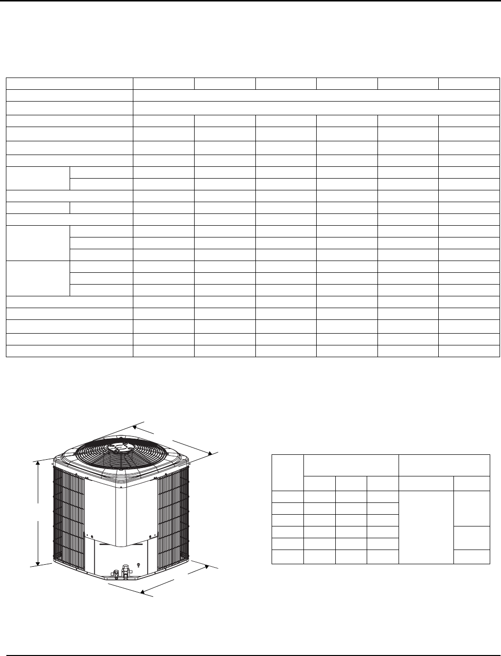
Johnson Controls Unitary Products 362564-UTD-B-0708TABULAR DATA SHEETOutdoor Split System Air Conditioner 2 Thru 5 TonsMODELS: TCGF24* THRU 6014.5 SEE

Page 2 - 362564-UTD-B-0708

362564-UTD-B-07082 Johnson Controls Unitary ProductsR-410A SYSTEM CHARGING PROCEDUREAdditional R-410A Charge / Orifice Size for Various Matched System

Page 3

362564-UTD-B-0708Johnson Controls Unitary Products 3R-410A SYSTEM CHARGING PROCEDUREPROCEDURES:1. Unit factory charge listed on the unit nameplate inc

Page 4 - *362564*

Subject to change without notice. Printed in U.S.A. 362564-UTD-B-0708Copyright © 2008 by Johnson Controls, Inc. All rights reserved. Supersedes: 36256

Comments to this Manuals

No comments